This device can be used to remotely control the speed of an AC fan and to switch it on or off. The remote control is a cheap NEC Format remote, usually supplied with small DVD players. Three buttons are used to command the circuit. The UP key increase the fan's speed while the DOWN key decrease it. The ENTER key is used to switch on or off the fan. The unit provides 10 way speed control from 0 to 9. The current speed is displayed in a seven segment display. The yellow LED on the PCB indicates the power status of the load. If the load is switched off using the R/C then the LED will also be switched off.
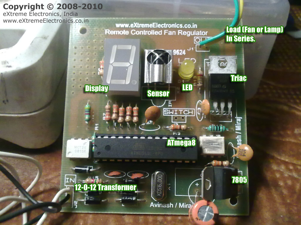
The main parts of the circuit is labeled below.
|
Fig.: Atmel AVR Based Remote Controlled Fan Regulator. |
 |
Fig.: Remote Controlled Fan Regulator Wiring Diagram. |
You can make the circuit as per the schematic on any general purpose PCB. To ease your job we are giving the PCB Layouts too, so that you can make the PCB at your home using the Etching Method. You may also have the PCBs made from any fab house too. To further easy the job and save your money we have already made the PCBs from a good fab house and they are available for purchase at very low cost.
Start assembly process by first soldering the jumper1. Then you can mount the resistors. After that solder the diodes, remember to properly orient the diodes. They are polar and don't work if installed other way round. Then solder the IC U4 and U2, this time too take care of the orientation. The small round circle on the IC package marks the PIN number 1.
 |
Fig.: Proper IC Installation. |
After that you can solder the ceramic disk capacitors, the 16MHz crystal, 7805, Triac, TSOP Sensor, Display. Finally Connect the 12-0-12 Transformer and apply power. The display should show '0'. Then you can press the up/down key in remote control to adjust the speed. The display should change accordingly. This ensures that the circuit is running properly.
Its time to connect a real AC load. Connect a 220V 100W incandescent lamp (NO CFL Please). As shown in the above wiring diagram. Replace the fan with bulb because its easier to test.
| WARNING !!! |
| Never Touch any part of the circuit when AC load is connected. It can give you a fetal shock !!! |
Now you can can use the remote control to increase/decrease the lamp's brightness using the remote control. You can also switch it on and off using the ENTER key.
If the unit does not respond to the remote control signals then look for the following.
 |
Fig.: This Hobby Remote Control Works Great! |
Hobby Remote Control (NEC) is available from our online store.
Part List |
||
| 01 | 330 ohm resistor (8 Nos) | R2-R9 |
| 02 | 4k7 Resistor (2 Nos) | R1, ,R11 |
| 03 | 1K Resistor | R12 |
| 04 | 39 ohm Resistor | R13 |
| 05 | 1K5 Resistor | R15 |
| 06 | 22pF Ceramic Disk Capacitor (2 Nos) | C1,C2 |
| 07 | 0.1uF Ceramic Disk Capacitor (3 Nos) | C3,C5,C6 |
| 08 | 470uF 50v Electrolytic Capacitor | C4 |
| 09 | 16 MHz Crystal Half Size | X1 |
| 10 | 1N4007 Diode (6 Nos) | D2,D3,D4,D5,D6,D7 |
| 11 | LED 5mm Any Colour | D1 |
| 12 | MCT2E Opto Coupler | U4 |
| 13 | MOC3021 Opto Triac Driver | U2 |
| 14 | ATmega8-16PU General purpose 8 bit MCU | U1 |
| 15 | Triac BT136 | U3 |
| 16 | 7805 Voltage Regulator | U5 |
| 17 | Common Anode Display | DISP11 |
| 18 | TSOP1738 IR Sensor | X2 |
| 19 | 220V AC to 12-0-12 Centre Tapped Transformer (NOT Included in KIT) | |
| 20 | Hobby Remote Control (NEC) | |
Buy Remote Controlled Fan Regulator Kit.
 |
Fig.: Schematic (Click To Enlarge/Print). |
PCBs can be purchased from PCB section of our online shop.
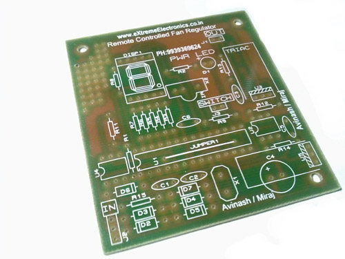 |
Fig.: Remote Controlled Fan Regulator PCB. |
/*

Remote Controlled Fan Regulator.

********************************

Compiler: avr-gcc (WinAVR-20090313)
Project Manager/IDE: AVR Studio 4.17 Build 666
Other Lib: eXtreme NEC Decoder.

Hardware:
   INT0 - IR Receiver
   INT1 - Zero Crossing Detector.

   PD5 - Triac Control.
   PB2 - Manual Switch

For
   ATmega8 @ 16MHz

Fuse:
   HIGH=0xC9 LOW=0xFF

   Copyright (c) 2008-2010
   eXtreme Electronics, India

                                     NOTICE
                           --------
NO PART OF THIS WORK CAN BE COPIED, DISTRIBUTED OR PUBLISHED WITHOUT A
WRITTEN PERMISSION FROM EXTREME ELECTRONICS INDIA. THE LIBRARY, NOR ANY PART

OF IT CAN BE USED IN COMMERCIAL APPLICATIONS. IT IS INTENDED TO BE USED FOR
HOBBY, LEARNING AND EDUCATIONAL PURPOSE ONLY. IF YOU WANT TO USE THEM IN
COMMERCIAL APPLICATION PLEASE WRITE TO THE AUTHOR.

*/


#include <avr/io.h>
#include <util/delay_basic.h>

#include <avr/interrupt.h>

#include "remote.h"
#include "rckeys.h"

#define FAN_POWER_LED_PORT PORTD
#define FAN_POWER_LED_DDR DDRD
#define FAN_POWER_LED_BIT 7

#define POWER_LED_ON()  FAN_POWER_LED_PORT&=(~(1<<FAN_POWER_LED_BIT))
#define POWER_LED_OFF() FAN_POWER_LED_PORT|=(1<<FAN_POWER_LED_BIT)

uint8_t table[10]={141,125,109,94,78,62,47,31,16,1};

uint8_t speed=0;
uint8_t fan_on=0;


void Initialize()
{
   FAN_POWER_LED_DDR|=0B10000000;

   POWER_LED_OFF();

   DDRC|=0b00111111; //Seven segment
   DDRB|=0b00000010; //Middle segment G

   Display(0);

   RemoteInit();

   //Initialize the zero crossing detector INT(1)

   MCUCR|=((1<<ISC11)|(1<<ISC10));     //INT in Rising edge
   GICR|=(1<<INT1);              //Enable INT1

   //Output

   DDRD|=(1<<PD5);
   PORTD|=(1<<PD5);  //High = TRIAC Off


   //Set Timer 2
   TCCR2|=(1<<WGM21);   //CTC

   TIMSK|=(1<<OCIE2);   //Enable OCI2

   sei();

}
/*

Zero Crossing Detect.

*/

ISR(INT1_vect)
{
   if(!fan_on)
   {
      PORTD|=(1<<PD5);  //High = TRIAC Off
      return;
   }

   if(speed==9)
   {
      PORTD&=(~(1<<PD5)); //low = TRIAC ON

      return;
   }

   PORTD|=(1<<PD5);  //High = TRIAC Off

   OCR2=table[speed];

   TCNT2=0x00;

   TCCR2|=((1<<CS22)|(1<<CS21)|(1<<CS20));   //Start Timer prescaler =1024

}

/*

Timer2 Compare ISR

*/
ISR(TIMER2_COMP_vect)
{
   PORTD&=(~(1<<PD5)); //low = TRIAC ON

   TCCR2&=(~((1<<CS22)|(1<<CS21)|(1<<CS20)));   //Stop Timer
}

/*

Simple Wait Function

*/
void Wait()
{
   char i;

   for(i=0;i<100;i++)
      _delay_loop_2(0);
}


/*

Displays a number in Seven Seg Display

*/
void Display(uint8_t num)
{
   if(num>9)
      return;

   switch (num)
   {
      case 0:
         PORTC=0B00000000;
         PORTB|=0B00000010;
         break;
      case 1:
          //      xxfedcba

         PORTC=0B00111001;
         PORTB|=0B00000010;
         break;
      case 2:
         //      xxfedcba
         PORTC=0B00100100;
         PORTB&=(~(0B00000010));
         break;
      case 3:
         //      xxfedcba

         PORTC=0B00110000;
         PORTB&=(~(0B00000010));
         break;
         break;
      case 4:
         //      xxfedcba

         PORTC=0B00011001;
         PORTB&=(~(0B00000010));
         break;
      case 5:
         //      xxfedcba
         PORTC=0B00010010;
         PORTB&=(~(0B00000010));
         break;
      case 6:
         //      xxfedcba

         PORTC=0B00000010;
         PORTB&=(~(0B00000010));
         break;
      case 7:
         //      xxfedcba
         PORTC=0B00111000;
         PORTB|=0B00000010;
         break;
      case 8:
         //      xxfedcba

         PORTC=0B00000000;
         PORTB&=(~(0B00000010));
         break;
      case 9:
         //      xxfedcba
         PORTC=0B00010000;
         PORTB&=(~(0B00000010));
         break;
   }
}


void main()
{

   uint8_t cmd; //Command received from remote

   Initialize();

   while(1)
   {
      //Get Command For the Remote Control
      cmd=GetRemoteCmd(1);

      //Now process the command

      //UP Key
      if(cmd==RC_UP)
      {
         if(speed<9)
            speed++;

      }

      //DOWN Key
      if(cmd==RC_DOWN)
      {
         if(speed>0)
            speed--;
      }

      //Enter Key

      if(cmd==RC_ENTER)
      {
         if(fan_on)
         {
            POWER_LED_OFF();
            fan_on=0;   //Turn Off
         }
         else
         {
            POWER_LED_ON();
            fan_on=1;   //Turn On

         }
      }

      Display(speed);

   }
}
Note: Other files that are part of the eXtreme NEC decoder must also be added to the project. They can be downloaded from links given below.
Buy complete kit including PCB, Parts, Programmed MCU and Matching IR Remote Control Unit. You just need to buy a 12-0-12 Transformer of current rating 500ma or more because it is NOT included in the kit.
Buy Remote Controlled Fan Regulator Kit.
By
Avinash Gupta
www.AvinashGupta.com
me@avinashgupta.com